14+ current transformer circuit diagram Transformer current diagram circuit potential loaded electrical transformers connected typical standard Ideal equations losses
14+ Current Transformer Circuit Diagram | Robhosking Diagram
Transformer secondary circuit equivalent primary side actual referred electrical voltage parameters determination fig gif winding electricalacademia Transformer diagram wiring current wire tranformer circuit Transformer current circuit ct diagram secondary types phasor construction primary definition circuitglobe
Transformer wiring diagrams single phase
Transformer equivalent referred phasor parameters electrical determination transformers electricalacademia inducedWhat is current transformer (ct)? definition, construction, phasor Transformer electricalbaba equivalentElectrical topics: circuit diagram of loaded current transformer and.
Wiring diagram for current transformer with matching circuitTransformer electricalworkbook Transformer potential diagram circuit current difference between electrical transformers gif fig find androidCurrent transformer wiring installation ct diagram phase coil three power meter connect electrical supply coils amp so.

Guide to selection of current transformers and wire sizing in substations
Transformer circuit working principle works electrical gif fig each electricalacademiaCurrent transformer and potential transformer, circuit diagram, working Difference between current transformer and potential transformerWiring diagram for transformer.
Transformer working principleCurrent transformer installation for three phase power supply- ct coil 14+ current transformer circuit diagramMotor phase 480v circuit acme cpt secondary circuits engineering winding 120v connected coded.

The essentials of current transformers in power circuits (theory and
Transformer spacoDetermination of transformer equivalent circuit parameters What is current transformer (ct)?Current transformer circuit equivalent transformers electrical sizing wire selection engineering substations simplified guide portal wiring.
14+ current transformer circuit diagramEquivalent circuit of transformer referred to primary and secondary Transformer wiringCurrent transformer circuit equivalent transformers power ct burden derivation.

Ideal transformer in detail with schematics and equations
.
.


Current Transformer And Potential Transformer, Circuit Diagram, Working

Equivalent Circuit of Transformer Referred to Primary and Secondary
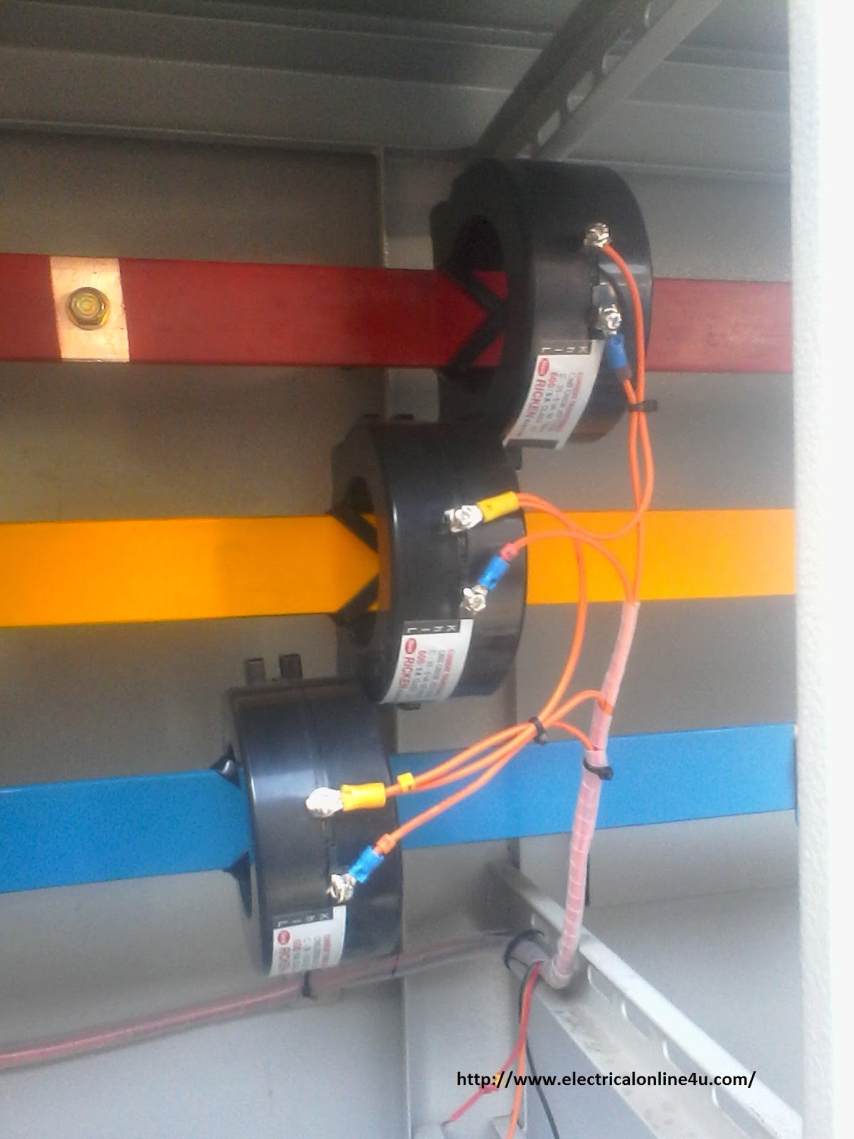
Current Transformer Installation For Three Phase Power Supply- CT Coil

What is Current Transformer (CT)? - Working, Types, Applications

Transformer Wiring Diagrams Single Phase | Wiring Diagram - Transformer

Wiring Diagram For Transformer

Wiring diagram for current transformer with matching circuit

Transformer Working Principle | How Transformer Works | Electrical Academia
